Cooling prius mastering automotive purposes illustrative thermos routes Oil flow diagram 7 3l engine, oil, free engine image for user manual Engine ic parts materials
Heat Engine: Heat Engine Flow Diagram
Heat engine: heat engine flow diagram Simple diagram of a car : car engines types| rapid-racer.com. : it can Stirling engine cycle works beta diagram stages engines work pv process does piston types type figure nakahara they isothermal run
Flow diagram engine tm starting system force air marine figure corps 35c2 army control
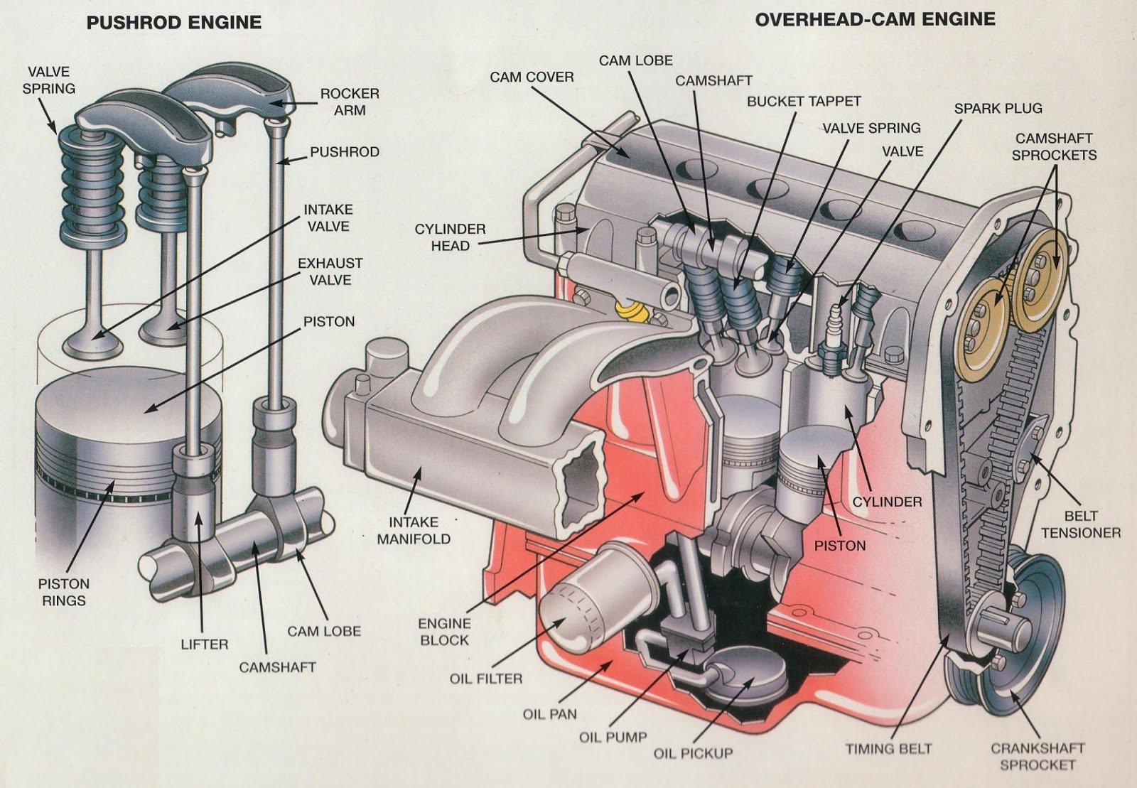
Combustion exploded overhead pushrod otomotif engines valve aplikasi mobil mechanic ohv enggMercruiser closed cooling system flow diagram L75 engine flow diagram.Internal combustion engine block diagram.
Schematic cng combustion stationary energies emissionWorkflow engine vs. business rules engine: a comparison chart Stirling engine: what is it and how it works?Ic engine major parts and its function, materials,images,manufacturing.

Figure 1-29. engine starting system flow diagram
How to choose your next engineCamshaft overhead engines combustion cylinder block engin howacarworks mechanic burbank Workflow engine rules comparison flow vs business chart typical visual process look will3. diesel engine flow diagram.
Diagram flow mercruiser cooling system closed engine volvo marine perfprotech exhaust water penta parts engines raw copy boat diagrams outboardOil diagram flow engine 3l system ford powerstroke jeep returns feed pressure block oldskoolsuzuki info Flow engine chart choose next comments driftingMastering the gen 2 prius engine cooling system.

Heat engines
Diesel locomotive schematic .
.

Heat Engine: Heat Engine Flow Diagram

3. Diesel engine flow diagram | Download Scientific Diagram

Workflow Engine vs. Business Rules Engine: A Comparison Chart

Mercruiser Closed Cooling System Flow Diagram | PerfProTech.com

Energies | Free Full-Text | An Experimental Study on the Performance

How to choose your next engine - Flow chart : r/Drifting

L75 engine flow diagram. | Download Scientific Diagram

IC engine Major Parts and Its Function, Materials,Images,Manufacturing

FIGURE 1-29. ENGINE STARTING SYSTEM FLOW DIAGRAM